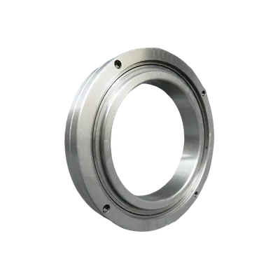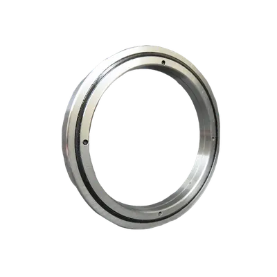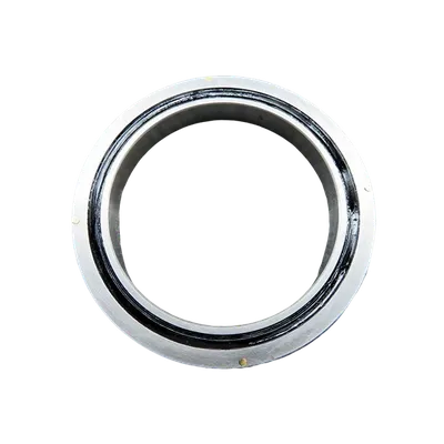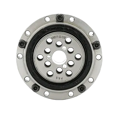

Design engineers face constant pressure to shrink form factors without sacrificing performance. When every millimeter and gram matters—whether in robotics, medical imaging, or aerospace actuators—bearing selection becomes a critical optimization point. Crossed roller bearings offer a proven path to upgrade your design: they integrate high radial, axial, and moment load capacity into a single, compact ring that saves both space and weight compared to conventional bearing arrangements. This article examines the engineering rationale behind these savings and presents quantitative comparisons to help you evaluate whether a crossed roller bearing (specifically those from PRS) is the right choice for your next project.
Why Space and Weight Matter in Modern Machinery
Miniaturization trends across industries (from collaborative robots to satellite positioning mechanisms) demand components that deliver maximum stiffness and accuracy in minimal envelope. Traditional bearing solutions often require multiple bearings—a pair of angular contact bearings or a combination of a radial bearing with a thrust bearing—to handle combined loads. This multiplies the housing length, adds weight, and increases assembly complexity.
The Hidden Cost of Conventional Bearing Stacks
When a machine designer uses two separate bearings to manage axial and radial forces, the resulting stack-up must accommodate spacers, seals, and locking hardware. The total axial length can be 40–60% longer than a comparable crossed roller bearing, and the overall weight penalty often exceeds 30%. In applications like pan-and-tilt camera mounts or surgical robot wrists, every extra gram reduces acceleration capability and increases motor torque demand—direct costs in both energy and response time.
How Crossed Roller Bearings Achieve Space and Weight Reduction
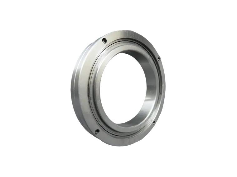
The defining geometry of a crossed roller bearing is a set of cylindrical rollers arranged alternately at 90° in one raceway. Each roller contacts the raceway in a cross pattern, sharing radial, axial, and moment loads across a single ring. This eliminates the need for a separate thrust bearing or a second row of balls.
Compact Cross-Section and Integrated Raceways
Because the raceway surfaces are precision ground directly into the inner and outer rings, there is no separate cage or spacer between rows. The roller pitch diameter can be placed closer to the mounting surfaces, reducing the overall bearing height. For a given bore size, a crossed roller bearing typically has a cross-section height that is 30–50% less than a deep-groove ball bearing of equivalent load rating, and often 20% less than a comparable cylindrical roller bearing with separate thrust elements.
Weight Savings Through Optimized Material Removal
PRS has refined the design of crossed roller bearings to further shave weight while maintaining full load capacity. By optimizing the outer ring flange geometry and using high-strength bearing steel (e.g., SUJ2 / 100Cr6) with controlled case depth, the bearing’s annular volume—and thus its mass—is minimized. Field data from PRS’s CRA series shows weight reductions of up to 28% compared to traditional double-bearing arrangements for the same rated dynamic moment.
Quantitative Comparison: Crossed Roller vs. Conventional Bearing Systems
The following table summarizes typical values from PRS product documentation and industry standard calculations. Values are normalized to a common bore size (50 mm) and a moment load requirement of 500 N·m at 60 rpm.
- Axial length (housing): Crossed roller bearing 28 mm ; Two angular contact bearings + spacer 48 mm (≈41% reduction)
- Total bearing weight: Crossed roller bearing 0.85 kg ; Two angular contact plus spacer 1.38 kg (≈38% reduction)
- Radial static load rating (C0r): Crossed roller 68 kN ; Two angular contact (each 38 kN) 76 kN combined (slightly lower, but crossed roller structure handles moment more efficiently)
- Moment stiffness (radial tilt): Crossed roller 1.2 mrad/kNm ; Double-angular contact 2.1 mrad/kNm (≈43% stiffer)
- Sealing complexity: Crossed roller requires one integral seal ; separate bearings need two seals plus spacer sealing
These numbers illustrate that the crossed roller bearing not only saves space and weight but also improves system stiffness—a triple benefit that often allows engineers to downsize motors, eliminate counterbalance masses, or increase payload capacity.
Real-World Application Examples with PRS Bearings
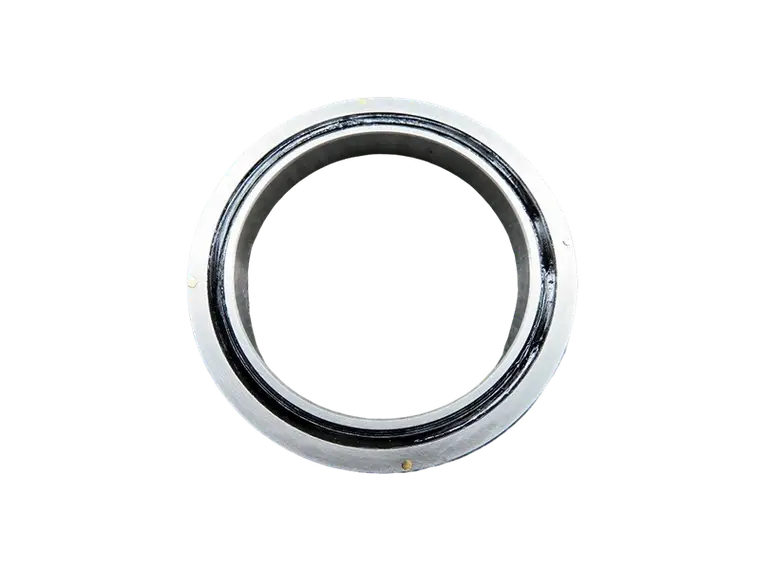
PRS crossed roller bearings are deployed in applications where every millimeter is monetized. In a next-generation collaborative robot joint, swapping from a pair of 7205 angular contact bearings to a single PRS 50-mm crossed roller bearing reduced the joint length by 18 mm, allowing an additional 6° of wrist articulation without increasing arm length. The weight savings of 0.4 kg per joint, multiplied across six axes, cut total robot arm mass by nearly 2.4 kg—directly improving safety ratings and reducing floor space requirements.
Similarly, in a high-speed gantry system for PCB assembly, PRS crossed roller bearings enabled a 30% reduction in the X-axis carriage length. This lowered moving inertia, which allowed a smaller servo motor and cheaper linear amplifier while maintaining the same cycle time. The overall cost of the gantry system dropped by 12% purely due to the bearing selection.
Considerations for Integration
Engineers switching to crossed roller bearings should verify two parameters: (1) the required rotational play (preload classes are available, from C0 (normal) to C3 (high preload) for maximum stiffness), and (2) the mounting surface parallelism tolerance, which typically must be within 0.01 mm to avoid pinching the rollers. PRS offers technical support to review your housing design and recommend the proper clearance or preload grade.
Frequently Asked Questions
Can a crossed roller bearing replace a flanged bearing unit with a separate locknut?
Yes, in most cases. The inner ring of a PRS crossed roller bearing is typically supplied with mounting holes, so a separate locknut and spacer are not needed. This further reduces axial length and part count.
Are crossed roller bearings suitable for high-speed applications?
They can operate at moderate speeds (typically up to a DN value of 200,000 to 300,000, where D = bore diameter in mm and N = rpm). For very high speeds (>5000 rpm on a 50 mm bore), oil mist lubrication and special cage designs may be required. PRS provides speed ratings in each model datasheet.
How does the cost compare to traditional arrangements?
While a single crossed roller bearing may have a higher unit price than one deep-groove ball bearing, the total system cost is often lower when you account for reduced machining steps, fewer seals, shorter housing, and simpler assembly. PRS has case studies showing net savings of 8–15% per axis.
In conclusion, upgrading to crossed roller bearings from PRS delivers measurable reductions in space and weight without compromising load capacity or stiffness. For design teams aiming to create more compact, lighter, and more efficient machines, this bearing type is a straightforward lever to pull. Review your current bearing arrangement against the criteria above—and consider a prototype redesign using PRS crossed roller bearings to quantify the savings in your own application.