
Crossed roller bearings are often specified when a single bearing must carry radial load, axial load, and tilting moment at the same time. Their cylindrical rollers are arranged at 90-degree intervals on one raceway, so alternating rollers take the load in different directions. That layout lets a compact bearing behave like two separate bearings fitted into one envelope. Understanding how the rollers share radial and axial forces helps engineers decide whether a crossed roller bearing is the right choice, and how to size it correctly. The sections below explain the load paths inside the bearing, the factors that limit capacity, and the design decisions that determine real-world performance.
Why the Crossed Roller Arrangement Changes Load Behaviour
A standard ball bearing handles radial load well but offers limited axial capability unless it is designed with a contact angle. A crossed roller bearing solves the problem geometrically rather than by adding a second row in a separate housing.
Alternating 90-degree roller orientation
The rollers sit in a V-shaped raceway with a 90-degree included angle. Adjacent rollers are turned 90 degrees to each other, so the load line of one roller is perpendicular to the load line of its neighbour. Because each load line sits at roughly 45 degrees to the shaft axis, a roller can respond to both a radial and an axial force component at the same time. Under pure radial load, approximately half the rollers are loaded in compression along one diagonal; under axial load, the other set engages. This is why the bearing is described as capable of carrying loads in all directions with a single raceway pair.
Line contact instead of point contact
Cylindrical rollers touch the raceway along a line, not at a point. Compared with a ball of similar envelope size, the contact area is far larger, so the stress per unit area is lower for a given load. The practical result is higher radial and axial stiffness and less elastic deflection under the same force. That stiffness is usually the reason a designer moves from a ball bearing to a crossed roller design in the first place.
How Radial Loads Are Distributed Inside the Bearing
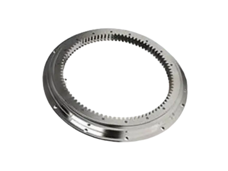
When a radial force is applied, the rollers whose load lines have a vertical component take the load and pass it into the housing wall. Several factors govern how evenly that happens:
- Radial internal clearance or preload — a preloaded bearing engages more rollers from the start and deflects less.
- Raceway roundness and housing bore tolerance — out-of-round seats concentrate load on a few rollers.
- Roller diameter consistency and spacer quality — uneven rollers create uneven load sharing.
- Shaft and housing rigidity — elastic deformation of surrounding structures can exceed the bearing's own deflection.
Because the load zone in a crossed roller bearing is wider than in a comparable ball bearing, the bearing tolerates a slightly misaligned or deflecting support structure better, provided the misalignment stays within the manufacturer's stated limit.
How Axial Loads Travel Through the Raceway
Axial load enters through the side face of the inner or outer ring and is transferred to the rollers whose load lines are angled toward the direction of the force. Each engaged roller then presses against the V-groove flanks on both sides, which is why a crossed roller bearing can be preloaded axially without a separate thrust washer.
Axial stiffness and deflection
Axial deflection in a crossed roller bearing is typically low, because the axial force is shared among many rollers in line contact. For positioning applications such as rotary tables, index heads, and robot joints, this low, predictable deflection is often more important than the headline load rating. A bearing that is strong enough but deflects unevenly will still produce positioning error.
Combined Radial, Axial, and Moment Loading
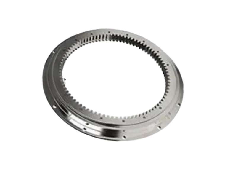
Most real applications do not apply radial and axial loads in isolation. A moment load, or tilting moment, is what occurs when force is applied at a distance from the bearing centre — for example at the edge of a rotating table. A crossed roller bearing resists this because the rollers on opposite sides of the ring are loaded in opposite directions, forming an internal couple.
When radial, axial, and moment loads act together, they cannot simply be added together numerically. Each contributes to the peak stress at the most heavily loaded roller, and the combined effect must be compared against the bearing's static and dynamic rating curves. This is one reason selection should be based on the actual load case rather than a single catalogue number. Suppliers such as PRS typically provide load capacity curves that let engineers plot a combined load point and confirm it falls inside the safe envelope.
What Determines Real Load Capacity
The catalogue rating is only one part of the answer. In service, capacity is limited by the weakest element in the chain:
- Roller and raceway material and hardness — through-hardened or case-hardened steel grades set the fatigue limit.
- Preload level — preload improves stiffness but consumes part of the available capacity.
- Mounting accuracy — flatness and perpendicularity of the seating faces directly affect load sharing.
- Lubrication and sealing — inadequate lubrication shortens life long before the load limit is reached.
- Operating speed and duty cycle — continuous rotation and shock loading demand a larger safety margin.
Selection and Installation Points That Protect Capacity
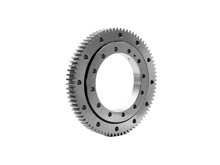
A crossed roller bearing performs as designed only when the surrounding structure supports it. Machined seating faces should meet the flatness and perpendicularity tolerances given for the bearing series, and clamped rings should be tightened evenly to avoid distorting the raceway. Where the bearing is split — most commonly the outer ring, sometimes the inner ring — the joint must be aligned precisely, since a step at the joint interrupts the roller path and creates a local stress peak on every pass.
Preload should be chosen to match the application. Positioning systems benefit from a higher preload because it removes clearance and raises stiffness. Applications with heavy external loads and limited drive torque may need a lighter preload to preserve running capacity.
Frequently Asked Questions
Can a crossed roller bearing carry pure axial load?
Yes. The angled load lines mean axial force is transmitted through the same V-groove raceways used for radial load. The allowable axial load is generally lower than the allowable radial load for a given bearing size, so the axial figure should always be checked separately.
Does preload increase load capacity?
No. Preload increases stiffness and improves load sharing, but it uses up part of the bearing's capacity before any external load is applied. The usable capacity for external load is therefore slightly lower in a preloaded bearing.
Why does mounting accuracy matter so much?
Because the rollers work in line contact, a small tilt or an out-of-flat seat shifts load onto a narrow band of rollers. That concentrates stress and reduces fatigue life far more quickly than the same misalignment would in a ball bearing.
Handling radial and axial loads in one compact bearing is the core advantage of the crossed roller design, but that advantage depends on correct sizing, sensible preload, and rigid, accurately machined mounting surfaces. Engineers who evaluate the combined load case rather than the radial rating alone will get predictable stiffness, long service life, and positioning accuracy that holds up over years of operation.