

Crossed roller bearings deliver the stiffness and rotational accuracy that machine tools, robotics, and metrology equipment demand. Yet those same qualities make them unforgiving during installation. A few micrometers of misalignment, uneven preload, or contamination at the mounting surface can raise runout, generate heat, and cut service life short. This guide outlines practical mounting steps that help engineers and technicians preserve the precision built into every crossed roller bearing.
Why Crossed Roller Bearings Are Sensitive to Mounting Errors
Unlike deep groove ball bearings that tolerate some misalignment without immediate consequences, crossed roller bearings rely on line contact between cylindrical rollers and raceways. The rollers alternate in a 90-degree crossed arrangement, allowing one bearing to handle radial, axial, and moment loads simultaneously. That design delivers high rigidity, but it also means any mounting deviation transfers directly to the rolling contact zone.
The geometry leaves little room for error
Because the rollers are preloaded against flat raceways, the bearing's internal clearance is measured in microns. When the housing or shaft face is not parallel within specification, the outer or inner ring distorts. The distortion redistributes load unevenly across the rollers, concentrating stress on a few contact points and causing premature fatigue. Rotation accuracy suffers as a result, showing up as axial runout or radial wobble.
Temperature compounds the problem. A bearing installed with uneven preload will generate localized heat during rotation. That heat expands the rings differently, which can either increase preload to dangerous levels or reduce it until clearance appears. Both outcomes degrade precision.
Preload, clearance, and stiffness
Preload is the small axial force applied to eliminate internal clearance and increase rigidity. In crossed roller bearings, preload is typically set by the bearing manufacturer or achieved through shimming and adjustable mounting structures. Too little preload leaves clearance that allows deflection under load. Too much preload raises friction torque and accelerates wear. The mounting process must preserve whatever preload condition the application requires, without introducing additional stress.
Pre-Installation Checks and Preparation
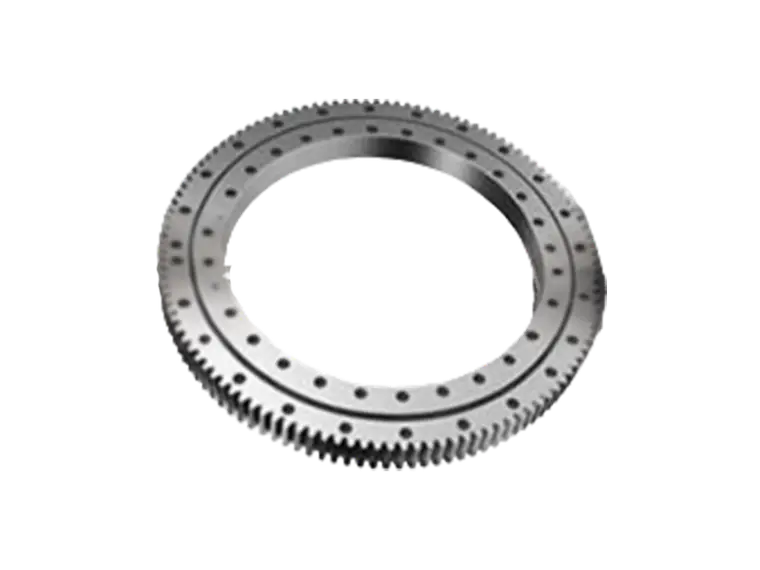
Precision begins before the bearing touches the shaft. Preparing the mating components correctly prevents most installation-related failures.
Inspect the bearing and mating surfaces
- Verify the bearing part number, internal clearance, and preload specification against the application drawing.
- Check the shaft shoulder and housing face for flatness, perpendicularity, and surface finish. Typical requirements call for flatness within a few micrometers and surface roughness below Ra 0.8.
- Look for burrs, nicks, or handling damage on the bearing rings. Even a slight raised edge on a mounting face can tilt the ring.
- Confirm that the housing bore and shaft diameter meet the specified tolerance range. Interference fits that are too tight distort the outer ring; fits that are too loose allow creep.
Clean the environment and components
Contamination is a leading cause of early bearing failure. Clean the mounting area with lint-free wipes and an approved solvent. Avoid compressed air that may carry moisture or particles. If the application demands extreme precision, perform the installation in a controlled environment where temperature and airborne particles are managed. Allow the bearing and mating parts to reach room temperature before assembly to avoid thermal expansion errors during fit-up.
Step-by-Step Mounting Practices for Precision
The sequence below reflects established practice for crossed roller bearings used in high-accuracy rotary tables, robot joints, and indexing heads.
Positioning and alignment
Never force a bearing onto a shaft or into a housing. Use a press or a controlled temperature differential if an interference fit is required, and apply force only to the ring being fitted. Striking the wrong ring can brinell the raceways or displace the rollers. For separable designs, guide the inner ring and outer ring together to avoid skewing the roller set.
Use a dial indicator to check concentricity and perpendicularity as the bearing seats. If the bearing uses a locating shoulder, confirm that the ring contacts the shoulder evenly around its circumference.
Applying preload
When the design uses an adjustable preload nut or shim pack, tighten gradually and in stages. Measure rotation torque or axial displacement at each stage to confirm that preload is increasing smoothly. Abrupt jumps in torque often indicate that a ring is cocked or that contamination has entered the raceway.
For shimmed designs, calculate the shim thickness from the measured gap rather than estimating. Over-shimming increases preload beyond specification; under-shimming leaves clearance.
Fastening sequence and torque control
Use a calibrated torque wrench and follow a cross or star pattern when tightening clamp rings, housing bolts, or retaining plates. Tighten in several passes at increasing percentages of final torque. This method distributes clamping force evenly and prevents the ring from distorting. If the application requires thread locking, choose a compound that will not wick into the bearing cavity.
Common Mounting Mistakes That Cost Precision
Most accuracy problems traced back to installation share a small set of root causes:
- Applying mounting force through the rolling elements instead of the fitted ring.
- Skipping the cleanliness check and trapping particles between mating surfaces.
- Tightening fasteners in a single pass or in a circular sequence, which tilts the ring.
- Assuming the housing face is flat without measuring it.
- Setting preload by feel rather than by measurement.
- Ignoring temperature differences between the bearing and the housing during assembly.
Each of these errors is avoidable with basic metrology tools and a disciplined procedure. The cost of a dial indicator and a torque wrench is negligible compared with the cost of replacing a damaged precision bearing or scrapping a finished assembly.
Verifying Accuracy After Installation
Once the bearing is mounted, verify that the installation preserved the intended precision. Measure axial and radial runout at the mounting face with a high-resolution indicator. Rotate the assembly slowly and watch for periodic variation, which suggests raceway distortion or uneven preload.
Run the assembly at low speed and monitor temperature rise. A properly installed crossed roller bearing should stabilize within a narrow temperature band. A steady upward drift indicates excess preload or insufficient clearance. If vibration analysis is available, check for frequency peaks that correspond to roller pass or raceway defects.
PRS recommends documenting the measured runout, preload torque, and temperature profile for each unit. This record becomes a baseline for maintenance decisions and helps distinguish installation issues from normal wear.
Frequently Asked Questions
Can a crossed roller bearing be remounted after removal?
In many cases yes, but only after inspecting the raceways and rollers for damage. Reusing a bearing that was installed with excessive preload or contamination may carry hidden fatigue into the new assembly.
How do I know if preload is correct?
Measure rotation torque or axial displacement and compare it against the bearing manufacturer's specification. If no specification is available, consult the application engineer before running the assembly under load.
What surface finish is required on mounting faces?
A ground surface with flatness within a few micrometers and roughness below Ra 0.8 is typical for precision applications. Rougher surfaces reduce the effective contact area and can shift preload as the bearing settles.
Final Considerations
Precision in a crossed roller bearing assembly is not a property of the bearing alone. It is the result of careful preparation, controlled force, measured preload, and verification at every stage. By treating mounting as a metrology-driven process rather than a mechanical chore, technicians protect the bearing's internal geometry and the accuracy of the entire machine. The tips above apply broadly, but every application has specific tolerances and load conditions. Working with an experienced bearing supplier early in the design phase can prevent mounting problems before they reach the assembly floor.