

Selecting a crossed roller bearing is rarely a matter of picking a part number from a catalog. Because these bearings carry radial, axial and moment loads at the same time inside a single compact unit, the choice directly determines the rigidity, positioning accuracy and service life of the whole axis. This guide walks through the criteria engineers actually use — load analysis, stiffness, accuracy grade, mounting geometry, lubrication and operating environment — and shows how to turn those criteria into a specification a supplier can quote against. Whether you are designing a rotary table, a robot joint or a semiconductor handling stage, the same sequence of decisions applies.
Why Crossed Roller Bearings Get Specified
In a crossed roller bearing, cylindrical rollers sit in a V-shaped raceway and are arranged alternately at 90 degrees to one another. Instead of the point contact found in ball bearings, the rollers make line contact with the raceway, and the 90-degree arrangement means each roller set resists load in a different direction. The result is a bearing that handles radial load, axial load and tilting moment simultaneously.
For machine designers this solves a practical problem. A conventional arrangement might need two angular contact bearings, a thrust bearing and a housing machined to hold them all in the right relationship. A single crossed roller bearing delivers comparable or better stiffness in a much shorter axial envelope. That is why the design shows up in rotary indexing tables, articulated robot arms, machine tool C-axes, radar pedestals, medical scanning gantries and wafer-handling robots — applications where a few micrometers of tilt or runout would compromise the process.
Core Selection Criteria
Load capacity and load direction
Start with the load case, not the catalog page. Establish the radial force, the axial force, and the moment arm acting on the bearing, including the inertia loads during acceleration and any off-center payload. Crossed roller bearings are usually rated with a dynamic radial capacity, a dynamic axial capacity and an allowable moment, and the limiting one is rarely the same in every application. A vertical rotary axis with an offset tool load is often moment-limited; a horizontal indexing table may be limited by radial load instead. Add a safety factor that reflects the consequences of failure and the certainty of the load estimate, and remember that shock and vibration from the machine itself belong in the calculation too.
Rigidity and preload
Stiffness is what separates a precision axis from an approximate one. Preloading the bearing removes internal clearance and eliminates the dead band that would otherwise appear when the load reverses direction. Light preload is usually enough for positioning axes that mostly see steady loads; heavier preload raises stiffness further but also raises friction torque, running temperature and drag. In practice, manufacturers offer defined preload classes and matched spacer rings, which is far more reliable than trying to set preload on the machine with shims. If your application involves servo hunting, contouring error or a tool that must not deflect under cut, specify the stiffness target first and let it drive the preload choice.
Accuracy grade and runout
Rotational accuracy is quoted as a tolerance class rather than a single number. Grades such as P5, P4 and P2 describe progressively tighter limits on the radial runout of the inner and outer rings, and they matter most when the bearing's runout is a meaningful fraction of your total error budget. Two practical reminders: the gear or encoder you mount on the bearing inherits its runout, and a high-accuracy bearing installed against a poorly machined shoulder will not perform to grade. Accuracy is a property of the assembly, not just the component.
Speed, lubrication and sealing
Allowable speed depends on the roller arrangement, the cage design, the lubricant and how the heat leaves the bearing. Grease is the default for most industrial axes, with oil or oil-air lubrication reserved for continuous high-speed duty or for cases where the bearing must also act as a heat path. Sealed and shielded versions keep contamination out but add friction; open bearings in a clean, oil-lubricated housing run cooler. In vacuum, cleanroom or food-processing environments, the lubricant and any seal material often become the deciding factor rather than the bearing geometry itself.
Envelope, mounting and environment
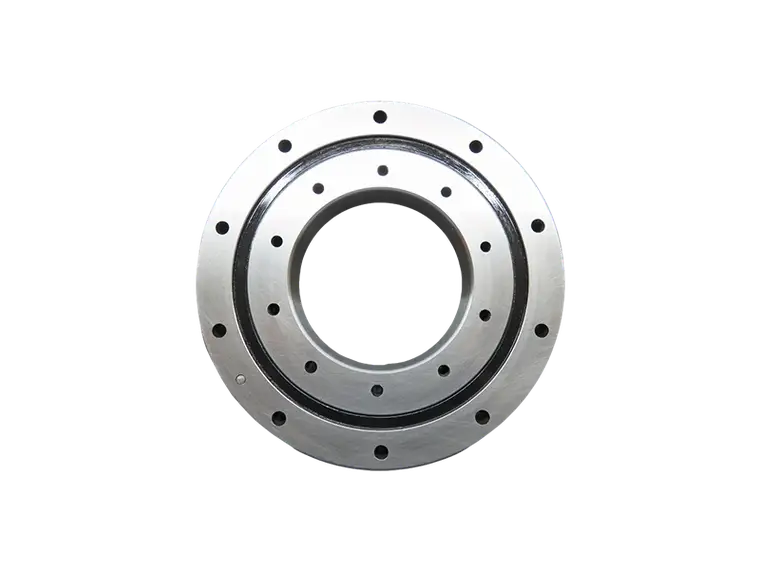
Confirm the available axial height, the bore and outside diameter, and how the bearing will be fixed. Some designs are supplied with mounting holes in the inner and outer rings so the bearing bolts directly to a housing and a table; others rely on clamp plates or end caps. Space saved here is often the reason the crossed roller design was chosen in the first place, so it is worth checking early whether the standard series offers the combination of bore, height and mounting pattern your design needs.
Comparing Configurations: Which Type Fits Your Axis
Once the load case is clear, the remaining decision is which construction to use. The main practical advantages of a crossed roller bearing over the alternatives are worth stating plainly:
- One bearing, three load directions. Radial, axial and moment loads are carried by a single unit, replacing multi-bearing arrangements.
- High rigidity per unit of height. Line contact and a short, wide raceway keep deflection low in a compact axial envelope.
- High rotational accuracy. Tight runout tolerances support precise positioning on rotary and indexing axes.
- Simplified housing design. Fewer machining operations, fewer shoulders to control, fewer fits to stack up.
- Predictable preload. Defined preload classes allow consistent stiffness across production units.
Within the family, the common choices are:
- Split inner ring designs, typically used where the inner ring rotates and the outer ring is fixed to the housing.
- Split outer ring designs, used where the outer ring rotates and the inner ring is fixed to a shaft.
- Integrated designs with mounting holes in both rings, chosen for maximum rigidity and the lowest possible assembly height.
- Thin-section variants, chosen when the available radial space is the binding constraint.
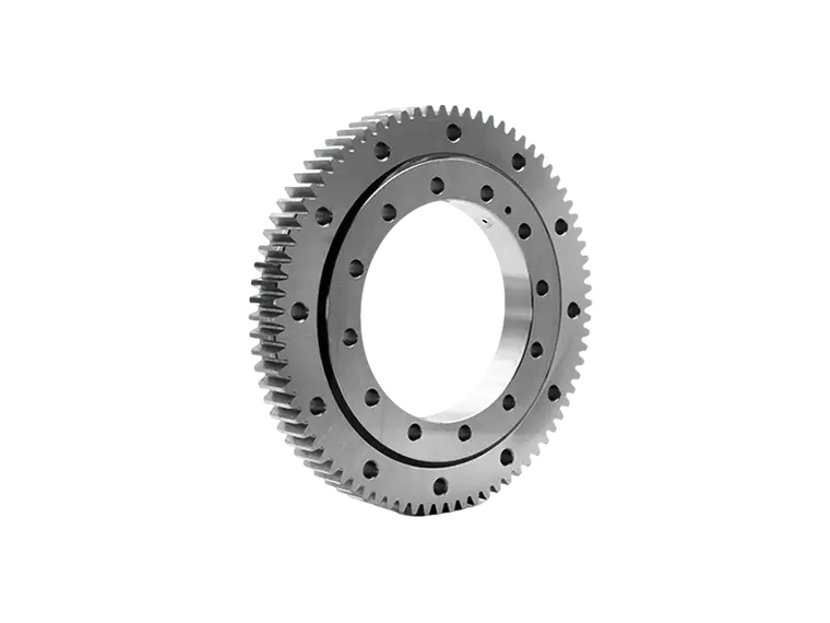
A slewing ring may still be the better answer for very large diameters, slow rotation and heavy overturning moments. A pair of angular contact bearings remains reasonable when loads are purely axial and radial and cost is the dominant driver. The crossed roller design wins when compactness, stiffness and accuracy must all be satisfied at once.
Mounting and Installation Practices
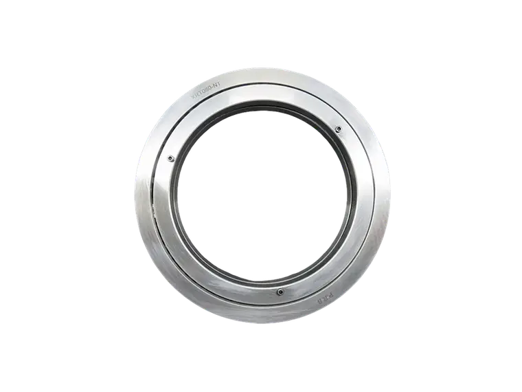
Most premature failures in precision bearings are installation problems, not design problems. The mating surfaces must be flat and parallel within the tolerance your accuracy grade demands; a bowed housing will distort the raceway and consume the clearance or preload you paid for. Tighten mounting bolts in a diagonal sequence in several passes rather than fully torquing one bolt at a time, since uneven clamping is a common source of local deformation and noisy rotation. Check shaft and housing fits against the manufacturer's recommendations — for precision axes, interference fits that are too tight can reduce internal clearance, while fits that are too loose allow the ring to creep. Finally, verify runout after assembly, not just on the bench, so that any stack-up error is caught before the machine ships.
Building a Specification for Quotation
A clear request produces a faster and more accurate quotation. Include the following:
- Bore, outside diameter and axial height, with any hard envelope limits marked.
- Radial load, axial load and moment, with the safety factor you intend to apply.
- Required accuracy grade and the allowable runout of the assembled axis.
- Speed range, duty cycle and expected operating temperature.
- Lubrication preference, sealing requirement and environmental conditions such as vacuum, washdown or contamination.
- Mounting method — bolted, clamped, or with a matched spacer — and whether a rotary table or gear is attached.
- Target service life in revolutions or hours, and the maintenance interval the machine can accept.
Suppliers who build bearings specifically for precision motion can often recommend a preload class and mounting arrangement from this information alone. Working with a manufacturer such as PRS, which produces crossed roller bearings for rotary and linear positioning applications, shortens the loop between the load case and a viable part number, and it makes the preload, tolerance and lubrication assumptions explicit rather than implied.
Frequently Asked Questions
Can a crossed roller bearing handle radial and axial loads at the same time?
Yes. The alternately crossed rollers mean the bearing supports radial load, axial load in both directions and tilting moment simultaneously, which is the main reason it can replace a multi-bearing arrangement.
Do I always need preload?
Not always. Preload is essential when the load direction reverses, when stiffness drives positioning accuracy, or when the axis must resist vibration. For slow, lightly loaded, unidirectional applications, a small clearance may be acceptable and will run cooler.
What limits bearing life most often?
Contamination, inadequate or degraded lubrication, and mounting surfaces that are not flat or parallel. Load-related fatigue is real, but installation and lubrication issues usually appear first.
How do I choose between a crossed roller bearing and a slewing ring?
Diameter and load magnitude decide it. Crossed roller bearings suit compact, high-accuracy axes with moderate moments. Slewing rings suit large diameters, slow rotation and very heavy overturning loads.
Conclusion
Selection starts with an honest load case and ends with a specification that states preload, accuracy grade and lubrication explicitly. Work through load, stiffness and runout in that order, choose the ring configuration that matches which part rotates, and treat mounting flatness and bolt sequence as part of the design rather than a detail for the assembly floor. Do that, and the bearing will deliver the rigidity and positioning accuracy the axis was designed around for its full service life.