

Robotic joints are the mechanical heart of any articulated system, whether it is a six-axis industrial arm, a collaborative robot on a production line, or a mobile manipulator navigating a warehouse floor. Every degree of freedom a joint delivers depends on how precisely its bearing assembly handles combined radial, axial, and moment loads, often inside a housing barely larger than a human wrist. Crossed roller bearings have become the default answer for these positions because they combine high stiffness, near-zero clearance, and a compact envelope in a single unit. This article explains how they function inside robotic joints, where they outperform alternatives, and what to verify before specifying one.
Why Robotic Joints Are a Demanding Bearing Environment
A robot joint rarely sees a single, predictable load direction. During a pick-and-place cycle, the shoulder of a six-axis arm may experience radial force from the payload, axial thrust from acceleration, and a tilting moment from the offset center of gravity, all at the same time. Add repeated reversals, intermittent dwell periods, and the requirement to hold position within arc-seconds, and the bearing becomes a structural element rather than a simple rolling interface.
Three requirements dominate joint design:
- High tilting stiffness. Any compliance at the joint multiplies through the kinematic chain and shows up as positional error at the tool center point.
- Zero or preloaded clearance. Backlash cannot be compensated by software without sacrificing repeatability.
- Compact axial height. Joint housings are constrained by the arm geometry, so the bearing must deliver stiffness without adding length to the axis.
Standard deep groove or angular contact ball bearings handle only part of this load case. Two bearings mounted apart can share the moment, but they consume axial space and introduce stack-up tolerance that must be controlled across two seats instead of one.
How Crossed Roller Bearings Solve the Joint Problem
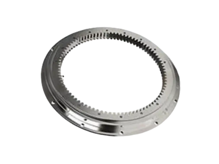
A crossed roller bearing places cylindrical rollers in a single raceway, alternating orientation so that adjacent rollers sit at 90 degrees to each other. Spacers or a cage keep them separated and evenly distributed. The result is a bearing that accepts radial, axial, and moment loads simultaneously from one compact ring.
Load capacity in a reduced envelope
Because the rollers contact the raceway along a line rather than a point, the load-carrying area is substantially larger than an equivalent ball bearing of the same diameter. This allows a crossed roller bearing to match the capacity of a paired angular contact arrangement while using roughly half the axial height. For a robot joint, that saved space translates directly into a shorter, lighter arm segment.
Stiffness and positioning accuracy
Line contact also produces a steeper load-deflection curve. Under the same moment, a crossed roller bearing deflects less than a ball bearing, which preserves the stiffness of the joint under dynamic acceleration. When the bearing is preloaded, internal clearance is eliminated, so the joint does not rock between forward and reverse motion. This is the characteristic that makes crossed roller bearings suitable for the wrist and elbow axes of high-precision arms, where repeatability targets are measured in micrometers.
Integrated raceways and simplified assembly
Many crossed roller bearings are supplied as complete units, with inner and outer rings already matched and preloaded at the factory. The joint designer machines a single housing bore and a single shaft seat rather than two of each. Fewer interfaces mean fewer tolerance stacks, less shimming during assembly, and more predictable performance after the robot is rebuilt in the field.
Crossed Roller Bearings vs. Alternative Joint Solutions
The comparison below reflects the trade-offs a design engineer typically weighs when selecting a bearing for a robotic joint. The right choice depends on the axis, the payload, and the required service life, but the pattern is consistent across most articulated robots.
- Crossed roller bearing: one unit handles radial, axial, and moment loads; high tilting stiffness; compact axial height; preloaded for zero backlash; moderate cost; requires a flat, rigid mounting surface.
- Paired angular contact ball bearings: good radial and axial capacity; lower moment stiffness unless widely spaced; larger axial stack; more sensitive to preload adjustment during assembly.
- Thin-section ball bearing: lightweight and inexpensive; limited moment capacity; deflection under load can compromise joint accuracy; best suited to low-torque or non-critical axes.
- Harmonic drive integrated bearing: combines reduction and support in one package; excellent for high-ratio joints; restricted to specific gearbox interfaces and less flexible for custom geometries.
For the load-bearing axes of an industrial arm, the crossed roller bearing usually wins on the combination of stiffness, height, and backlash. Ball-based solutions remain viable where loads are light and cost dominates.
Selection Criteria for Robot Joint Bearings
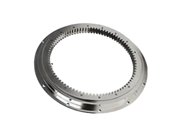
Specifying the correct bearing is not simply a matter of matching bore diameter to shaft size. Several parameters interact, and a change in one often forces a change in another.
- Moment load rating. Calculate the maximum tilting moment at the joint, including payload, arm mass, and dynamic acceleration. Compare it against the bearing's permissible moment curve, not just its static rating.
- Required stiffness. Determine the maximum allowable deflection at the joint under peak load. This often sets the preload level and the roller diameter.
- Speed and lubrication. High-speed joints may need oil or a controlled grease quantity to limit heat generation. Sealed, greased-for-life units suit slower axes with limited maintenance access.
- Mounting accuracy. Crossed roller bearings are sensitive to housing roundness and flatness. A soft or distorted housing will transfer its error into the raceway and shorten life.
- Environment. Washdown, vacuum, and cleanroom applications each call for different sealing and lubrication strategies.
Getting these five factors aligned before the housing is machined avoids the most common cause of premature joint failure: a bearing that was correct on paper but installed in a seat that could not support it.
Where PRS Fits Into the Supply Chain
PRS works with robot builders and integrators to match crossed roller bearing geometry to specific joint envelopes. That includes standard catalog sizes as well as modified rings, custom preload, and application-specific sealing. Because joint performance is determined by the bearing and its housing together, early involvement in the design phase usually reduces both the iteration count and the risk of a late-stage redesign.
Frequently Asked Questions
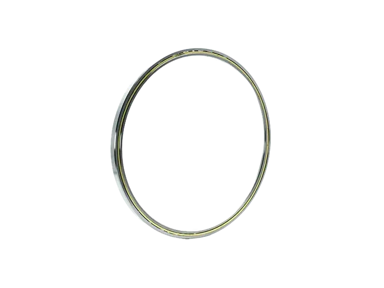
Can a crossed roller bearing replace two bearings in an existing joint design?
In many cases, yes. The single unit can carry the combined load that previously required a pair, but the housing must be re-evaluated for stiffness. A bearing that is structurally adequate can still perform poorly if the surrounding housing deflects under load.
How much preload is appropriate for a robot joint?
Preload should be sufficient to eliminate clearance under the maximum expected moment, but not so high that it increases friction and heat. The correct value depends on the bearing size and the stiffness target, and is usually specified with the bearing supplier rather than chosen from a table.
Are crossed roller bearings suitable for collaborative robots?
Yes. Cobots often have strict requirements for low backlash and compact joint modules, both of which favor crossed roller designs. Sealing and lubrication must be selected for the duty cycle and any washdown or cleanroom exposure.
Conclusion
A robotic joint is only as accurate as the bearing that locates it. Crossed roller bearings address the combined load, stiffness, and space constraints that define modern joint design, and they do so in a single preloaded unit that simplifies both the housing and the assembly process. The engineering work lies in specifying the right moment rating, preload, and mounting conditions for each axis. Handled correctly, the bearing becomes one of the most reliable elements in the robot; handled casually, it becomes the source of positioning errors that no control algorithm can fully correct.