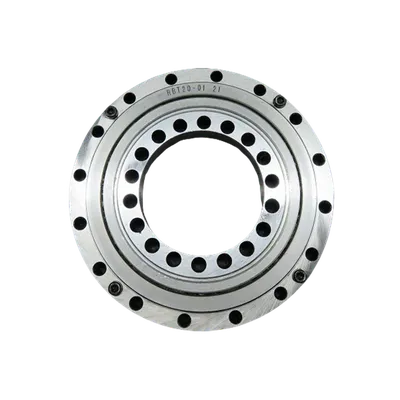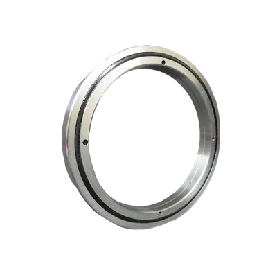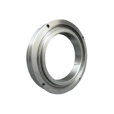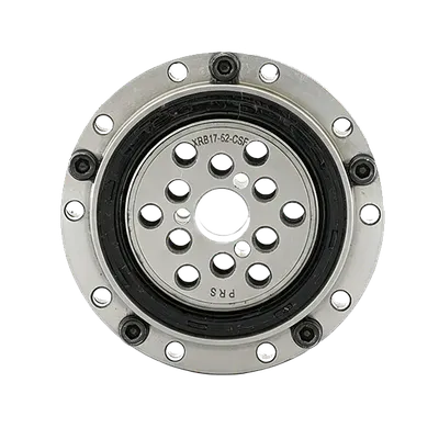

Crossed roller bearings are essential components in robotics, precision rotary tables, medical equipment, and semiconductor manufacturing systems. Their defining feature—cylindrical rollers arranged in a 90-degree alternating pattern within V-shaped raceways—allows a single bearing to simultaneously handle radial, axial, and moment loads. For engineers, accurately calculating load capacity is critical: underestimating it leads to premature failure, while overestimating it results in oversized, costly designs. This article explains the methods behind crossed roller bearing load capacity calculation, the factors that influence load ratings, and how to apply these results in real-world selection.
Understanding Load Characteristics in Crossed Roller Bearings
What Makes Crossed Roller Bearings Different
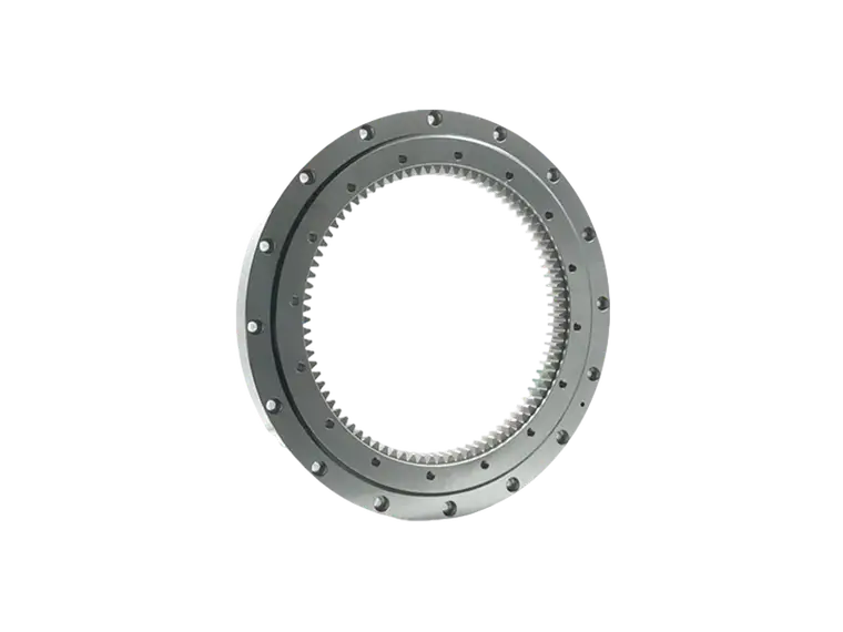
In a crossed roller bearing, cylindrical rollers are mounted in V-shaped raceways and arranged so that adjacent rollers are perpendicular to each other. This 90-degree cross pattern means each roller effectively supports load in only one direction, but the combined arrangement enables multi-directional load support. Compared to ball bearings, the line contact between rollers and raceways distributes load over a larger area, delivering significantly higher stiffness and load capacity within the same envelope.
Radial, Axial, and Moment Loads
Crossed roller bearings are typically subjected to three types of loads, often acting simultaneously:
- Radial loads: Forces perpendicular to the bearing axis. These are carried by rollers oriented perpendicular to the load direction.
- Axial loads: Forces parallel to the bearing axis. These are carried by rollers oriented parallel to the load direction.
- Moment loads: Tilting forces that create a non-uniform load distribution across the rollers, with one side of the bearing carrying more load than the other.
Because the rollers are crossed at 90 degrees, approximately half of the rollers contribute to radial load support and the other half to axial load support at any given time. This division is fundamental to crossed roller bearing load capacity calculation.
Calculating Basic Load Ratings
Basic Dynamic Load Rating (Cr)
The basic dynamic load rating represents the constant load under which a group of identical bearings can achieve one million revolutions before the onset of fatigue spalling, with a 90% reliability rate. For crossed roller bearings, the calculation follows the general roller bearing formula but accounts for the 90-degree cross arrangement:
Cr = fc × (le × cos 45°)^(7/9) × (Z/2)^(3/4) × Dwe^(29/27)
Where:
- fc = a coefficient determined by bearing geometry and material
- le = effective contact length of the roller
- Z = total number of rollers in both directions
- Dwe = roller diameter
The division of Z by 2 reflects that only the rollers oriented in the load direction contribute to load support in a given direction. The 45-degree contact angle accounts for the V-shaped raceway geometry.
Basic Static Load Rating (C0r)
The basic static load rating is the load that produces a permanent deformation of 0.0001 times the roller diameter at the most heavily loaded contact point. This rating is critical for applications involving slow rotation, intermittent motion, or stationary loads. The formula is:
C0r = f0 × le × cos 45° × (Z/2) × Dwe
Where f0 is a factor dependent on the contact geometry and allowable permanent deformation. The static rating ensures that the bearing does not suffer excessive deformation under peak loads, which is especially important in robotics and automation where positioning accuracy is paramount.
Equivalent Load for Combined Loading
In most practical applications, crossed roller bearings experience simultaneous radial, axial, and moment loads. To evaluate whether a bearing can handle a given application, engineers calculate the equivalent load (P) using the following general form:
P = X × Fr + Y × Fa + Zm × M
Where Fr is the radial load, Fa is the axial load, M is the moment load, and X, Y, and Zm are coefficients provided by the bearing manufacturer. These coefficients depend on the specific internal geometry and contact angle of the bearing. Once the equivalent load is determined, it can be compared directly to the dynamic load rating to estimate bearing life using the life equation:
L10 = (Cr / P)^(10/3) × 10^6 revolutions
The exponent 10/3 applies to roller bearings, reflecting the line contact fatigue behavior.
Key Factors Influencing Real-World Load Capacity
Calculated load ratings assume ideal conditions. In practice, several factors can reduce or alter the actual load capacity of a crossed roller bearing:
- Roller geometry and manufacturing tolerance: Variations in roller diameter, length, or crown profile affect contact stress distribution. PRS maintains tight tolerances to ensure consistent load sharing across all rollers.
- Material hardness and quality: Bearing steel must achieve a minimum hardness of 58 to 62 HRC to support the calculated load ratings. Softer materials deform more readily under load.
- Lubrication: Proper lubrication prevents metal-to-metal contact and distributes load evenly across the roller-raceway interface. Inadequate lubrication can reduce load capacity by 30% or more.
- Mounting accuracy: Misalignment concentrates load on a subset of rollers, effectively reducing the number of load-bearing elements. A misalignment of just 0.001 radians can noticeably decrease capacity.
- Operating temperature: Elevated temperatures reduce material hardness and lubricant viscosity, diminishing both static and dynamic load capacities.
- Preload: While preload increases stiffness and eliminates clearance, excessive preload adds to the equivalent load and shortens bearing life.
Applying Load Calculations in Bearing Selection
Load capacity calculation is not an isolated exercise—it feeds directly into bearing selection and system design. Engineers should follow a structured approach:
- Define the load spectrum: Determine all radial, axial, and moment loads, including peak and continuous values.
- Calculate equivalent load: Use the manufacturer's coefficients to combine loads into a single equivalent load value.
- Apply a safety factor: Typically 1.5 to 2 for dynamic applications, and 2 to 3 for static or high-shock applications.
- Estimate life: Compare the equivalent load to the dynamic load rating and calculate L10 life. Verify that it meets the required service interval.
- Verify static capacity: Ensure that peak loads do not exceed the static load rating, especially during startup, shutdown, or emergency stops.
- Confirm stiffness and precision: In some applications, stiffness and running accuracy are as important as load capacity. Crossed roller bearings offer high stiffness, but preload and mounting must be optimized.
PRS supports engineers throughout this process by providing detailed load rating data, equivalent load coefficients, and application-specific recommendations. With accurate load calculations and the right bearing configuration, crossed roller bearings can deliver reliable performance for millions of cycles.
Frequently Asked Questions
How does the 90-degree roller arrangement affect load capacity?
The crossed arrangement means that only half of the rollers support load in any single direction. However, the overall load capacity remains high because the line contact of the rollers distributes stress more effectively than point contact in ball bearings. The trade-off is that the bearing must be sized to accommodate the divided load paths.
Can I use the dynamic load rating for static applications?
No. The dynamic load rating assumes rotation and fatigue failure mode. For static or very slow-moving applications, the static load rating (C0r) is the correct parameter. Using the dynamic rating in a static application may lead to excessive deformation and loss of precision.
What safety factor should I apply?
A safety factor of 1.5 to 2 is common for continuous dynamic operation. For applications with shock loads, frequent starts and stops, or high-precision requirements, a factor of 2 to 3 is recommended. The exact value depends on the consequences of failure and the accuracy of the load data.
Does preload increase load capacity?
Preload increases stiffness and eliminates internal clearance, which improves positioning accuracy. However, it also adds to the equivalent load on the bearing. The net effect is a trade-off: higher preload improves rigidity but reduces the available load capacity for external loads and shortens fatigue life.
Accurate load capacity calculation is the foundation of reliable crossed roller bearing selection. By understanding the static and dynamic ratings, accounting for combined loads, and applying appropriate safety factors, engineers can ensure that their systems achieve the required performance and service life. PRS provides comprehensive technical data and engineering support to help you through every stage of the calculation and selection process.