How Crossed Roller Bearings Improve CNC Rotary Axis Performance
2026-07-27 02:39:22PRS Bearings
In modern CNC machining, rotary axes are critical for multi-axis positioning and contouring. The performance of a rotary axis—its positional accuracy, repeatability, stiffness, and thermal stability—directly influences the quality of finished parts. Among the many components that determine these characteristics, the bearing system plays a central role. Crossed roller bearings have emerged as a preferred solution for CNC rotary tables, trunnions, and direct-drive rotary axes, offering distinct advantages over conventional ball or cylindrical roller bearings. This article explains the working principles of crossed roller bearings and demonstrates how they enhance rotary axis performance, backed by engineering rationale and practical considerations.
1. What Is a Crossed Roller Bearing and How Does It Work?
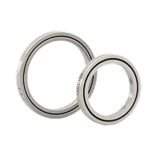
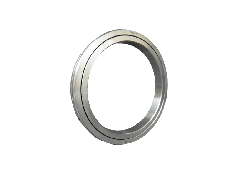
A crossed roller bearing is a type of rolling element bearing in which cylindrical rollers are arranged in crossed rows, typically with a 90-degree angle between the axes of adjacent rollers. The rollers are separated by spacers (or cage segments) to prevent contact and ensure smooth rotation. The raceways on the inner and outer rings are precision-ground to match the roller geometry, allowing the bearing to simultaneously support radial, axial, and moment loads with minimal deflection.
The key structural feature is the roller orientation: alternating rollers are placed at perpendicular angles (one set aligned vertically, the next horizontally). This design allows a single bearing ring to withstand loads from multiple directions without the need for multiple bearing pairs. The crossed arrangement also reduces internal clearance and increases contact area compared to point-contact ball bearings, resulting in significantly higher stiffness.
Roller Geometry and Material
Typical crossed roller bearings use cylindrical rollers made of high‑carbon chromium steel (e.g., SUJ2 equivalent) with hardness up to HRC 58–62. The rollers are precision ground to a tolerance of ISO Class 5 or better. The bearing rings are also heat‑treated and ground to ensure consistent preload and low running torque. Some advanced models incorporate ceramic rollers for reduced inertia and higher speed capability.
2. How Crossed Roller Bearings Enhance CNC Rotary Axis Performance
CNC rotary axes demand high stiffness to resist cutting forces, high accuracy to maintain positional repeatability, and high load capacity to support heavy workpieces. Crossed roller bearings directly address these requirements through the following mechanisms:
2.1 Superior Stiffness and Rigidity
Because the rollers make line contact with the raceways (as opposed to the point contact of balls), the elastic deformation under load is much smaller. This line contact provides up to 5–10 times higher static and dynamic stiffness compared to an equivalent‑size ball bearing. For rotary axes, higher stiffness means less deflection during heavy milling or turning, directly improving surface finish and dimensional accuracy.
2.2 Enhanced Load Capacity
The same line‑contact geometry allows crossed roller bearings to handle large axial loads, radial loads, and overturning moments simultaneously. A single crossed roller bearing can replace the combination of a ball bearing and a separate thrust bearing, simplifying the spindle design and reducing stack‑up tolerance errors. This makes crossed roller bearings ideal for compact rotary tables where space is limited.
2.3 Improved Rotational Accuracy and Repeatability
Crossed roller bearings are preloaded during assembly to eliminate internal clearance. Preload compresses the rollers against the raceways, creating a repeatable zero‑backlash condition. In a rotary axis, zero backlash ensures that the axis returns to the same angular position within arc‑seconds of error. Additionally, the crossed roller arrangement reduces axial runout and tilting errors because the rollers distribute loads evenly across the raceway.
2.4 Low Friction and Smooth Motion
Although line contact produces higher friction than point contact initially, crossed roller bearings are designed with optimized roller geometry and cage materials (often PEEK or brass) to minimize frictional torque. When properly lubricated, they exhibit very low starting and running torque—comparable to ball bearings—while maintaining high damping. This is crucial for direct‑drive rotary axes that require smooth motion at low speeds (e.g., 0.5–5 rpm) for heavy‑duty indexing.
3. Performance Comparison: Crossed Roller vs. Ball Bearings and Cylindrical Roller Bearings
To help engineers select the right bearing for a CNC rotary axis, the following table summarizes key performance parameters across three bearing types. Note that values are typical and may vary based on exact size and manufacturer.
- Stiffness (Radial/Axial): Crossed roller > Cylindrical roller > Ball bearing
- Moment Load Capacity: Crossed roller > Cylindrical roller > Ball bearing
- Rotational Accuracy (runout, tilt): Crossed roller > Ball bearing > Cylindrical roller
- Starting Friction: Ball bearing < Crossed roller < Cylindrical roller
- Speed Capability (max rpm): Ball bearing > Crossed roller > Cylindrical roller
- Required Axial Space: Crossed roller < Ball bearing + thrust bearing pair
For most CNC rotary axis applications requiring high static and dynamic rigidity with moderate speeds (<1000 rpm), crossed roller bearings offer the best balance. Ball bearings are still suitable for high‑speed spindles but are prone to deflection under heavy cutting. Cylindrical roller bearings excel in pure radial loads but require additional thrust bearings, adding complexity.
4. Practical Implementation and Supplier Considerations
Implementing crossed roller bearings in a rotary axis requires careful attention to mounting surfaces, preload adjustment, and lubrication. The bearing should be installed with a controlled interference fit on both the shaft and housing to maintain preload without causing excessive stress. Lubrication is usually grease‑packed for life or equipped with a central oil‑mist system for high‑duty cycles.
For OEMs and retrofitters looking to upgrade rotary axis performance, it is essential to partner with a supplier that can provide precision‑matched bearing pairs, technical support, and application engineering. PRS (Precision Roller Solutions) specializes in high‑accuracy crossed roller bearings for CNC machinery, offering standard series from 50 mm to 500 mm bore diameter as well as custom designs with integrated angle encoders or clamping systems. PRS bearings are manufactured to ISO P4/P2 tolerances and undergo 100% inspection for runout, torque, and noise.
Case Study: 5‑Axis Trunnion Table Upgrade
A machine tool builder replaced the original ball‑bearing‑based trunnion table on a 5‑axis machining center with PRS crossed roller bearings. The results: radial stiffness increased by 3.2×, tilting stiffness by 4.1×, and the table’s bidirectional repeatability improved from ±8 arc‑seconds to ±2 arc‑seconds. The customer reported a 25% reduction in scrap rate due to improved contour accuracy during simultaneous 5‑axis machining.
5. Conclusion
Crossed roller bearings provide a proven path to enhance CNC rotary axis performance by delivering superior stiffness, load capacity, accuracy, and low friction. When paired with proper design and installation, they enable machine tools to achieve tighter tolerances, better surface finishes, and longer service life. For engineers evaluating bearing options, the data clearly shows that crossed roller technology outperforms conventional ball and cylindrical roller bearings in most rotary axis scenarios. PRS stands ready to support these applications with expert guidance and precision components.


 XRT Series Crossed Tapered Roller Bearings
 XV Series Crossed Cylindrical Roller Bearing
 XRU Crossed Roller Bearings
 XRSU Crossed Roller Bearings
 XRE Crossed Roller Bearings
 XRC Crossed Roller Bearings
 XRBH Crossed Roller Bearings
 XRB Crossed Roller Bearings
 Ultra Thin XRBS Crossed Roller Bearings
 Ultra Thin XRA-C Crossed Roller Bearings
 Ultra Thin XRA Crossed Roller Bearings
 XRBC Crossed Roller Bearings